实验内容
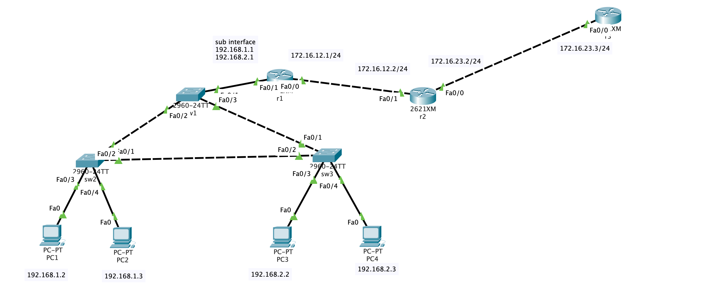
按照以下组网图把设备连接好(注意,R1的S1/0是DCE端,要在接口下用clock rate 64000来配置时钟频率);
按照拓扑图修改设备名,所有设备关闭域名解析,关闭自动退出。(考点-IOS基本操作)
PC1和PC2属于192.168.1.0网段,这个部门有20人,PC3和PC4属于192.168.2.0网段,这个部门有40人。请选择正确的子网掩码,要求最少浪费IP地址(考点–子网划分)
三台交换之间封装trunk(考点–trunk)
SW1,SW2,SW3属于同VTP域,域名ccna,其中SW1为server,SW2,SW3是客户端。SW1上建立VLAN10和VLAN20,SW2和SW3能够从SW1上学习到VLAN信息(考点–VTP)
将SW2上的F0/5和F0/6划进VLAN10,SW3上的F0/5和F0/6划进VLAN20.(考点–VLAN)
将SW2设为vlan10、vlan20的根桥。注意在两个vlan里都要设置(考点–STP)
在R1上配置单臂路由,注意SW1的F0/1封装trunk。(考点–单臂路由)
R1是公司内部路由,R2是边界,R1、R2运行RIP版本2协议,使公司内全通。(考点–RIP)
在R2上配置VTY,密码111,特权密码222,允许别人telnet。配置标准的ACL,应用到VTY接口下,使得只有PC1能够telnet R2(考点–telnet,ACL)
在R2上配置NAT,使192.168.1.0和192.168.2.0这两段内网地址在访问外网时全部转换为R2的S1/1接口地址。在R2上指一条0.0.0.0的默认路由,出接口S1/1(考点–NAT,静态路由)
实验过程
计算子网 考虑到”PC1和PC2属于192.168.1.0网段,这个部门有20人,PC3和PC4属于192.168.2.0网段,这个部门有40人。请选择正确的子网掩码,要求最少浪费IP地址”
1
2
20 = 0 b1010040 = 0 b101000
因此子网掩码的位数分别为32-5 = 27位, 0b11100000 = 224和32-6=26位, 0b11000000 = 192.
子网掩码可以分别设置为255.255.255.224和255.255.255.192.
配置truck 接下来在交换机的端口配置trunk.
1
2
Switch (config) #interface FastEthernet0/2 Switch (config-if) #switchport mode trunk
配置vtp SW1,SW2,SW3属于同VTP域,域名ccna,其中SW1为server,SW2,SW3是客户端。SW1上建立VLAN10和VLAN20,SW2和SW3能够从SW1上学习到VLAN信息
在SW1上:
1
2
3
4
5
6
7
8
9
10
11
Switch#vlan database Switch(vlan)#vtp server Device mode already VTP SERVER. Switch(vlan)#vtp domain ccna Changing VTP domain name from NULL to ccna Switch(vlan)#vlan 10 name VLAN10 VLAN 10 modified: Name: VLAN10 Switch(vlan)#vlan 20 name VLAN20 VLAN 20 modified: Name: VLAN20
在sw2和sw3上:
1
2
3
4
5
Switch#vlan database Switch(vlan)#vtp client Setting device to VTP CLIENT mode. Switch(vlan)#vtp domain ccna Domain name already set to ccna.
划分端口VLAN 将SW2上的F0/3和F0/4划进VLAN10,SW3上的F0/3和F0/4划进VLAN20
设置根桥 将SW2设为vlan10、vlan20的根桥。注意在两个vlan里都要设置
1
2
Switch(config)#spanning-tree vlan 10 root primary Switch(config)#spanning-tree vlan 20 root primary
单臂路由 在R1上配置单臂路由,注意SW1的F0/1封装trunk
1
2
3
4
5
6
7
8
Router (config) #int f0/1.1 Router (config-subif) #encapsulation dot1Q 10 Router (config-subif) #ip address 192.168 .1.1 255.255 .255.0 Router (config-subif) Router (config) #int f0/1.2 Router (config-subif) #encapsulation dot1Q 20 Router (config-subif) #ip address 192.168 .2.1 255.255 .255.0 Router (config-subif)
encapsulation dot1Q 10语句中最后的10是VLAN号, 不要弄错了
配置rip协议 R1是公司内部路由,R2是边界,R1、R2运行RIP版本2协议,使公司内全通
1
2
3
4
5
6
7
8
9
Router>en Router#configure terminal Enter configuration commands, one per line. End with CNTL/Z. Router(config ) #router ripRouter(config -router ) #version 2 Router(config -router ) #network 192.168 .2.0 Router(config -router ) #network 192.168 .1.0 Router(config -router ) #network 172.16 .12.0 Router(config -router ) #end
在PC1上测试:
1
2
3
4
5
6
7
8
9
10
11
12
13
C:\>ping 172.16 .12 .2 Pinging 172.16 .12 .2 with 32 bytes of data: Reply from 172.16 .12 .2 : bytes=32 time=8 ms TTL=254 Reply from 172.16 .12 .2 : bytes=32 time=17 ms TTL=254 Reply from 172.16 .12 .2 : bytes=32 time=2 ms TTL=254 Reply from 172.16 .12 .2 : bytes=32 time<1 ms TTL=254 Ping statistics for 172.16 .12 .2 : Packets: Sent = 4 , Received = 4 , Lost = 0 (0 % loss), Approximate round trip times in milli-seconds: Minimum = 0 ms, Maximum = 17 ms, Average = 6 ms
配置Telnet和ACL 在R2上配置VTY,密码111,特权密码222,允许别人telnet。配置标准的ACL,应用到VTY接口下,使得只有PC1能够telnet R2
先配置R2上的登陆环境:
1
2
3
4
Router (config) #enable secret 222 Router (config) #line vty 0 4 Router (config-line) #password 111 Router (config-line)
配置完毕后在R1上测试:
1
2
3
4
5
6
7
8
9
10
11
12
Router#telnet 172.16.12.2 Trying 172.16.12.2 .. .Open User Access Verification Password: Router>en Password: Router#exit [Connection to 172.16.12.2 closed by foreign host]
再配置ACL:
在R2上:
1
2
3
4
5
Router (config) #acc ess-list 101 permit tcp host 192.168 .1.2 host 172.16 .12.2 eq telnetRouter (config) #acc ess-list 101 deny tcp any host 172.16 .12.2 eq telnetRouter (config) #acc ess-list 101 permit ip any anyRouter (config) #int fa 0 /1 Router (config-if) #ip access-group 101 in
配置完成后测试:
在R1上:
1
2
3
Router#telnet 172.16.12.2 Trying 172.16.12.2 .. . % Connection timed out; remote host not responding
在PC1上:
1
2
3
4
5
6
7
8
9
10
C:\>telnet 172.16.12.2 Trying 172.16.12.2 .. .Open User Access Verification Password: Router>en Password: Router#
符合预期
配置NAT 在R2上配置NAT,使192.168.1.0和192.168.2.0这两段内网地址在访问外网时全部转换为R2的Fa0/0接口地址。在R2上指一条0.0.0.0的默认路由,出接口Fa0/0
1
2
3
4
5
6
7
8
9
Router(config)#interface fa0/0 Router(config-if)#ip nat outside Router(config-if)#int fa0/1 Router(config-if)#ip nat inside Router(config-if)#exit Router(config)#access-list 10 permit 192.168.1.0 0.0.0.255 Router(config)#access-list 10 permit 192.168.2.0 0.0.0.255 Router(config)#ip nat pool ippool 176.16.23.4 176.16.23.255 netmask 255.255.255.0 Router(config)#ip nat inside source list 10 pool ippool
添加静态路由 在R3上:
1 Router (config )#ip route 0.0 .0 .0 0.0 .0 .0 172.16 .23 .2
测试: 在PC1上ping r3, 然后查看R2的nat translation:
1
2
3
4
5
6
7
8
9
10
11
12
13
C:\>ping 172.16 .23 .3 Pinging 172.16 .23 .3 with 32 bytes of data: Reply from 172.16 .23 .3 : bytes=32 time=1 ms TTL=253 Reply from 172.16 .23 .3 : bytes=32 time<1 ms TTL=253 Reply from 172.16 .23 .3 : bytes=32 time=1 ms TTL=253 Reply from 172.16 .23 .3 : bytes=32 time<1 ms TTL=253 Ping statistics for 172.16 .23 .3 : Packets: Sent = 4 , Received = 4 , Lost = 0 (0 % loss), Approximate round trip times in milli-seconds: Minimum = 0 ms, Maximum = 1 ms, Average = 0 ms
1
2
3
4
5
6
Router #show ip nat translations Pro Inside global Inside local Outside local Outside global icmp 176.16 .23 .5 :89 192.168 .1 .2 :89 172.16 .23 .3 :89 172.16 .23 .3 :89 icmp 176.16 .23 .5 :90 192.168 .1 .2 :90 172.16 .23 .3 :90 172.16 .23 .3 :90 icmp 176.16 .23 .5 :91 192.168 .1 .2 :91 172.16 .23 .3 :91 172.16 .23 .3 :91 icmp 176.16 .23 .5 :92 192.168 .1 .2 :92 172.16 .23 .3 :92 172.16 .23 .3 :92